Wall-Mounted Foam Unit Foam Quality
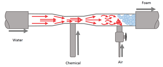
Below is an expanded view of the foam chamber/generator that has been rotated 90° to the left.
Functional Description:
Water enters the unit, typically from a city-pressure supply line, and passes through the foam chamber. As the water passes through the narrow section of the foam chamber, the velocity of the water increases. This causes a vacuum to form at the site of velocity/flow rate increase—this is called the “Venturi Effect”. This vacuum is used to draw concentrated chemical into the unit, where it is subsequently blended with the water.
Just downstream of the chemical injection, air is also introduced into the system. The air mixes with the water-chemical mixture to form foam. Just downstream of the air injection, there may be a packing material that is held in the foam chamber body by a screen. This packing material has a consistency similar to a scrub pad and it serves to enhance the foam consistency.
The chemical flow into the unit is regulated by a metering orifice that located in the black check-ball assembly to which the chemical tube is connected (see picture on left). The metering orifices come in various colors that represent different orifice sizes. The chemical tube should also have a strainer screen that prevents particulates and dried chemical residues from clogging the metering orifice.
Potential Causes of Poor Foam Quality:
- Hard water and/or hot hard water plumbed to the unit.
- Hard water can cause mineral to build up in the foam chamber and clog it
- Correct by running acid product through the foamer, or by complete disassembly and cleaning. After each use, the chemical pick-up line should be purged of chemical by placing it into a container of fresh water and activating the foamer until the unit is cleared of chemical.
- Metering orifice is clogged
- Clear obstruction or replace metering orifice
- Non-OEM parts used to repair unit
- Use only OEM parts for repair
- Connecting two hoses in series to enable reach to remote areas
- Foam units were designed to have a maximum of 50-75 ft hose, 5/8” to ¾” in diameter. Extending the length of the hose, or using one with a smaller diameter, will create too much back-pressure and will collapse the foam bubbles.
- Restrictions in the foam hose, such as installation of a hose swivel prior to the valve at the end of the hose, a restricted foam nozzle caused by dropping the foam wand on the floor, and installing a less than ½” full-port valve prior to the foam nozzle
- Remove any restrictions or non-OEM equipment from foam discharge hose. Replace any damaged nozzles or other components.
- Increasing air pressure to greater than the water pressure
- If the air pressure regulator is set so that the air pressure to the foam unit exceeds the water pressure, the unit will not properly draw up chemical and air can back up into the plant water supply line.
- Varying Plant Water Pressure
- During periods of high demand (ie…during sanitation activities), the plant water pressure can drop, causing the air pressure to exceed the water pressure to the unit. The only fix for this would be to use portable foam units with pre-mixed chemicals, or to install a central foam system that is not reliant upon plant water pressure.
Reach out to The RITE Team® for more information on wall-mounted foam stations.